Open Risco support portal including private FTP credentials

During a routine pen-test of an alarm receiving centre, I was googling for default usernames and passwords of Risco software and alarms.

When doing this, I found an abandoned support portal “Riscopedia” which contained a number of valid credentials for FTP sites, along with other private documentation.

Creds

Whilst the Technical.Notes account appears to be shut down, there are still paths onto other FTP servers that look like they should be closed.

This was reported to Risco on 30th July via Twitter and email.


Backdoor root account on Visonic Powerlink 2 modules

During a routine pen-test of an alarm receiving centre, a repository of manufacturer firmware was found. This is often quite hard to get hold of, and I welcomed the opportunity to reverse some of these.

The Visonic Powerlink 2 firmware stood out due to it’s large size – this was almost certainly an embedded Linux system.

On unpacking the firmware, it was found that the units had an enabled account with root privileges called root2 with the password visonic. I discovered this by cracking the password file. However, once I had done this, someone pointed out that this was widely documented as early as 2011.

The system runs telnet on port 7523, and a web interface on port 80. Shodan has ~85 of these visible at the moment.

Once you have root access, you can arm and disarm the connected alarm, and capture images from any connected cameras.

In addition to this, for the firmware and single unit I was permitted access to, it was found it was transmitting status messages (armed/disarmed status, serial number) over a plaintext connection to http://myhome.visonic.com/ (212.179.58.186). We could not find anywhere in the firmware to turn this off.

They would be an ideal pivot or persistance node in a longer term pen-test.


Vulnerability in password storage in Risco Configuration Software

During a routine pen-test of an alarm receiving centre, a piece of software was found that was used to remotely configure Risco alarms.

The software is backed by a SQL database called “ConfigurationSoftware” which contains a table called ut_Users with a column called PWD which stores passwords for users that can log into the system.

This PWD field appeared to be a base64 encoded string.

On further investigation, this password was stored in an encrypted form. This allows it to be recovered from the software, and doesn’t follow best practices of hashing passwords.

The encryption is AES-256 and uses a fixed key and IV which is hardcoded into the application.

Passwords were recovered from the database which, due to password re-use, allowed me to take control of the domain controller and website of the company. The password was of good complexity, so if hashing had been used, I would have been unlikely to have recovered this.

A Python script to decrypt the passwords is shown below.

from Crypto.Cipher import AES
from Crypto import Random
import base64

BS = 32
# PKCS #7
pad = lambda s: s + (BS - len(s) % BS) * chr(BS - len(s) % BS)
unpad = lambda s : s[0:-ord(s[-1])]

def encrypt(raw, key, iv ):
    raw = pad(raw)
    cipher = AES.new(key, AES.MODE_CBC, iv)
    return (cipher.encrypt(raw ))

def decrypt(enc, key, iv ):
    cipher = AES.new(key, AES.MODE_CBC, iv)
    return unpad(cipher.decrypt(enc))

# Static and hardcoded
key = 'FKLe608FDsF5J6ZaKpTghjED7Hb80ALq'
iv = 'Sckt6DopykVCD9Lq'

# The default 123 password as installed
ciphertext = 'BQqwo4a87TvfJKv4af8h3g=='

print 'Password is %s' % decrypt(base64.b64decode(ciphertext), key, iv).decode('utf-16-le')

This was reported to Risco on 7th August. A fix is meant to be deployed at the beginning of November.

Conclusion

  • Hash, don’t encrypt your passwords.
  • Don’t hardcode encryption keys in your software
  • Don’t use the same password for domain admin as in a system of unknown quality
  • Have a security contact so it’s not painful to report issues

iSmartAlarm – quick “teardown”

I noticed this post on the alarm forum at DIYnot. It mentions the iSmartAlarm – an alarm I’ve heard nothing about before. Smart tends to mean “connected to the Internet” which tends to mean “massive attack surface”, so I though I would have a quick look at the system and what is inside it.

The iSmartAlarm homepage is fairily standard. The alarm seems to comprise of a CubeOne at the heart of the system, with PIRs and door contacts connecting to it. The CubeOne appears to connect to your home router using a wired Ethernet connection.

iSmartAlarm

On the site, their is a manual for the alarm. It’s pretty sparse really – it doesn’t seem to have many features. There is also a section called “Port forwarding” on the support section. This only seems to be concern the iCamera they provide. Port forwarding is generally a Bad Thing™ as it lets someone outside of your NAT/firewall inside.

There is nothing really juicy there, we really need some pictures of PCBs to work out what is going on. No-one seems to have torn down one yet, so I’ve got to hope the FCC have something. Most wireless devices sold in the US need to be FCC compliant, which involves submitting test reports and internal photos to the FCC. There are a few ways out of this – using ready made wireless boards like the ElectricImp, and ticking all the boxes that make the documents confidential. Thankfully, most companies only request that the schematic, block diagram, and description of operation is confidential.

How to get the FCC ID? It’s not in the manual (it rarely is), so let’s look for a photo of one of the units.

cnet oblige with a photo of the bottom of one of the units.

FCC ID

Off we go to the FCC OET ID search. I haven’t worked out how to link to results on here, so just enter SENIPU3 as the ID and look for yourself.

The only really interesting document is the internal photos (reposted here).

One photo really stands out – the close-up of the PCB.

PCB shot

What do we have on here then?

First thing I see, upper right, is the venerable TI CC1110 chip. This is the same chip used in the IM-ME toy that has been changed into a spectrum analyser. It’s a combined microprocessor and sub-GHz RF frontend and is very flexible. To the right of it there is a pin header labelled CLK, D, RST, GND. These are the in-circuit programming pins for the CC1110 – you can see this on Travis Goodspeed’s page about hacking the IM-ME. Firmware recovery might be possible.

There is a Ralink RT5350F which appears to be a SoC used in a lot of wireless routers. It will be providing the wireless, Ethernet and USB. The datasheet indicates this boots from SPI serial flash, which means firmware recovery is almost certainly possible. I’m guessing the slightly frazzled looking 8-pin U10 is this device.

The big Winbond chip is SDRAM.

The funny little blue blob-on-board seems to be some kind of LED driver, judging by the proximity to the connections to the LED in the casing.

Not sure what the pin header at the top of the board is. JTAG on the Ralink chip is 5-pin. Could be a serial debug port.

Searching for the first three letters of the FCC ID brings up the other components – the PIR, door contact and fob. All using the CC1110. That means two-way comms is possible.

PIR

PIR

Door contact

Door contact

Fob

Fob

This system looks fairly hackable. The CC1110 data can be sniffed no doubt, firmware recovery may be possible. The Ralink firmware almost certainly can be recovered.

I wonder if it is worth getting hold of one?

WordPress escaping \ < > etc. in preformatted code – a quick fix

I’ve been posting code and paths regently use the <pre></pre> tags to preserve formatting. WordPress, however has other ideas, and removes the and changes the <> into escaped codes (&gt; &lt;), which display incorrectly inside <pre></pre>.

You can workaround this by editing outside WordPress, pasting in, and saving – it works fine the first time. This is really awkward though.

It seems installing this plugin:

http://wordpress.org/plugins/preserve-code-formatting/

Solves the problem by making sure everything inside <pre> is not messed with.

c:\text\
if A < C:

Wireless alarm recommendations

Several times I have been asked which wireless alarm system I would recommend, so I thought I would write a quick blog post.

I’ll start with some simple points:

  1. Wired is always going to be more secure than wireless – so if possible, go for a wired alarm. They are also cheaper, less prone to false alarms, and need less maintainence.
  2. An alarm install is more than the equipment. You need to think about which detection devices you need, where to place them, and what the alarm does when it goes off. You can buy the best equipment, install it badly, and have a poor alarm system. You could also buy mediocre equipment, install it well, and have decent alarm system.
  3. An alarm system that you do not use might as well be replaced with a bell box. Think about usability, maintenance, lifetime and so on when choosing.

I’ll also be realistic. At this point in time, home alarms are not being actively jammed, are not seeing replay attacks, encryption broken and so on.

I’d also recommend that a lot of people go with a professional installer. Alarms aren’t always easy – it’s definitely something that needs experience, especially if you want a neat and efficient install. There are a lot of great installers out there who really know what they are doing and take great pride in their work. There are also a number who don’t, so chose with care. I only have one piece of universal advice here – avoid ADT.

Alarms to avoid

Yale Wirefree

This uses one-way OOK 434MHz. This makes it very easy to jam (intentionally and unintentionally). It means that battery life is lower than it can be. There is very limited functionality.

On the upside, it is low cost, easy to setup, and the voice dialler is cheap.

Yale don’t seem very responsive or open about the limitations of this system.

Friedland Response

Uses one-way FSK 868Mhz. Very easy to jam, and battery life not as good as it can be. Functionality is incredibly limited on a lot of the alarms – there isn’t even a LCD display on many of them.

It is cheap though, and easy to setup.

Friedland aren’t very responsive about issues with this alarm – they requested that I don’t quote any of my communications with them.

Here is what they had to say though:

We have been selling wireless alarms since 1990 and code issues have never been a problem.
Potential burglars would need extensive knowledge and equipment to overcome any alarm system.
Most domestic burglaries are done by opportunists who would be put off breaking into an alarmed home and would not attempt to interfere with the alarm as they know this in itself would cause the alarm to activate, even if it wasn’t alarmed!

Alarms I’m not sure about

Scantronic/Cooper Ion

This is a 1-way system which has many of the disadvantages of the Yale Wirefree and Friedland Response. The actual alarm is a full featured grade 2 panel though, so it has that on it’s side.

In communication with Cooper, it doesn’t seem they realise how dangerous leaking firmware can be, how easy it is to disassemble.

I expect that some really clever person with a lot of time on their hands might figure out a way to poke around in the binary stuff and – eventually – figure out a way to do something mischievous but this would be fraught with all sorts of difficulties. But we are, of course, aware that eighteen year olds can hack into FBI computers from their bedrooms and so anything is possible given enough time and effort.

Yale Easyfit

This claims to use 868MHz, rolling codes, and better anti-jam functionality. I have one to test but haven’t had much of a look – it still looks to be a one-way system which really limits what you can do with rolling codes and jamming detection. The functionality is still very basic.

Honeywell Domonial

These seem to get put into new-builds a lot. I’ve been warned by installers these are hell to program, and this is coming from people who think the Honeywell Galaxy is a walk in the park.

Visonic PowerMax

I don’t like these guys as a company. The alarm system claims to be 2-way, but only a very limited number of components (not including the detectors) are 2-way. The alarm also claims to use FHSS but at 64hops/s using only 4 frequencies i.e. it’s token and will do little to improve security or interference immunity.

Being misleading like that makes me unhappy.

Alarms to buy

Pyronix Enforcer

Uses a two-way 868MHz protocol with encryption. This means jamming can be easily detected and detectors know when the system is armed or not, extending battery life. The system is grade 2 which means it could be professionally installed and insurance companies will take note.

The control panel and keypad are integrated (which is fairly rare in grade 2 alarms). This makes installing easier, but it is large and not very attractive. The LED colours are a bit bling and very bright.

The system is quite easy to setup with few pitfalls. Learn the detectors, chose zone and type, program some users and codes and it will work as a basic alarm.

There is a wealth of functionality such as soak tests, double knock triggering etc.

The alarm is readily available on eBay and other online sellers.

The wireless protocol isn’t perfect, but it is adequate for home use.

The manufacturer is responsive and upfront about potential issues with their system.

Texecom Premier Elite (Ricochet Technology)

Uses a two-way 868MHz protocol with encryption which builds up a wireless mesh network. Jamming can be detected and detectors know when the system is armed or not, extending battery life. The system is grade 2 which means it could be professionally installed and insurance companies will take note. 

The control panel and keypad are separate. This makes installing a little harder than the Pyronix, but it is more secure as the control panel can be hidden. The keypads are more discrete as well.

The system is relatively hard to setup compared to the Pyronix Enforcer. You need to have a better idea of what you are doing to get everything set correctly. I can easily see that you can program the alarm in a way which means it either wouldn’t alarm when it needed to, or would alarm when it didn’t need to (this is why professional installers exist!).

There is a lot of functionality in the system – the smaller panels are just cut down versions of the much larger ones.

The alarm is relatively hard to get hold of – eBay is your best bet. It’s really only marketed to professional installers.

The wireless protocol is very well designed.

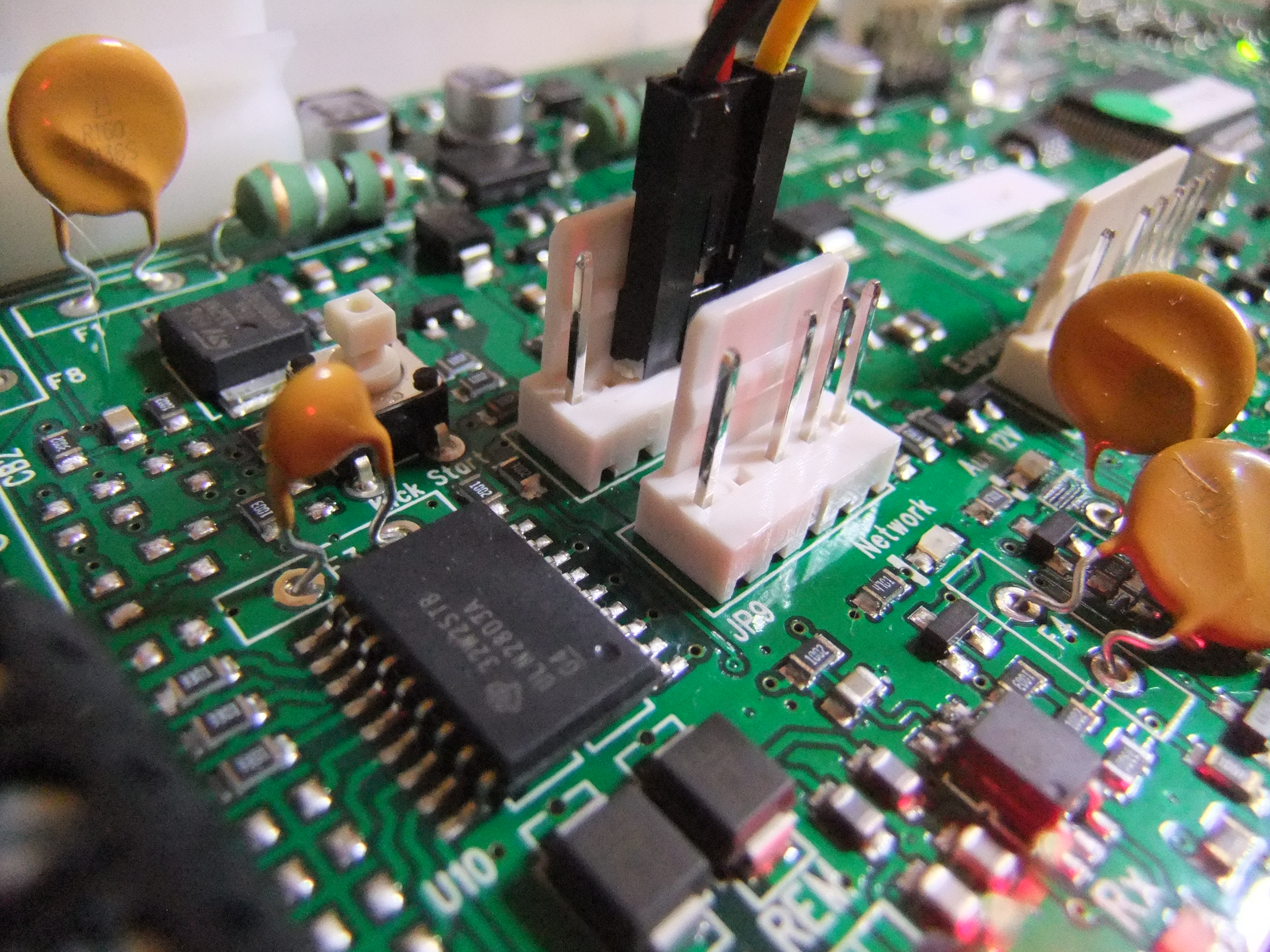
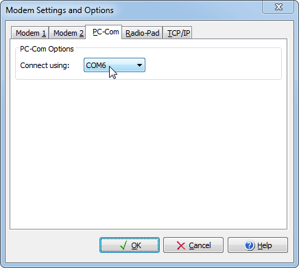
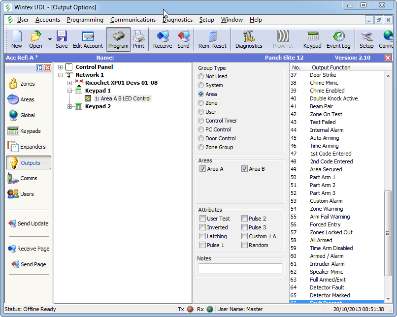
There is excellent software provided with the alarm that allows you to program it from a PC. This makes everything so much easier. You just need an FTDI cable to connect to the alarm.

The manufacturer actively engages with the installer community and myself about potential issues. Frequent firmware updates are available.

The alarm is designed and manufactured in the UK.

Programming a Texecom Premier Elite 12-W using a FTDI cable

The Texecom Premier Elite series of alarms can be programmed using Windows software called Wintex. This makes setting up these alarms far easier than using the keypad menus – they have hundreds of options and settings.

Texecom sell two products to connect to these alarms using Wintex – PC-COM (a serial port adapter ~£20) and USB-COM (a USB to serial adapter ~£35) . I strongly suspected these were just serial TTL converters, but I was concerned that there might be some jiggery pokery stopping this from working. Some software requires very specific VID (vendor ID) and PID (product IDs) on the USB device. Some software uses custom drivers. Others use microcontrollers and obfuscation to make sure you buy the genuine product.

As an avid hardware hacker, I have a lot of USB to TTL serial converters. The most useful (and reliable, in terms of drivers) are FTDI cables based on the FT232R chips. Genuine cables are ~£14, breakout boards can be as low as £2 on eBay. So let’s try and get connected to the Premier Elite 12-W using this cable.

There are two ports on the Premier Elite board – Com Port 1 and Com Port 2. These are 5 pin Molex connectors with only 4 pins populated. There didn’t seem to be a direct pin-out in the manual, so from the manual and with a multimeter we have:

Pin 1 – 12V

Pin 2 – nothing

Pin 3 – GND

Pin 4 – Receive

Pin 5 – Transmit

Com port 1 and 2

Com port 1 and 2

Signalling appears to be 5V. So, get out the 5V FTDI cable (they come in different voltages):

A 5V FTDI cable

A 5V FTDI cable

Pin 1 – GND

Pin 2 – Don’t care

Pin 3 – Don’t care

Pin 4 – Transmit

Pin 5 – Receive

Pin 6 – Don’t care

We then need to connect transmit to receive, receive to transmit, and common ground. This terminology might be at odds with alarm equipment – RS485 buses often label one wire “T” and it means transmit on the master, receive on the slave. I suspect this simplifies wiring as you just connect all “T” wires.

So, to connect the two:

Texecom – FTDI

Pin 3 GND – Pin 1 GND

Pin 4 Receive – Pin 4 Transmit

Pin 5 Transmit – Pin 5 Receive

Just be cautious of the 12V on pin 1 of the alarm board – sending this up the chuff of your PC will result in damage.

Using jumper cables, you could make up a proper cable

Using jumper cables, you could make up a proper cable

Find out which COM port the FTDI cable is using (generally go into Device Manager, and it will be listed there).

COM6 is my FTDI cable

COM6 is my FTDI cable

Go into Wintex and change the PC-COM port to this COM port:

Change Wintex to use COM6

Change Wintex to use COM6

Connect, receive settings, change settings, and monitor Ricochet devices to your heart’s content!

And start setting things up

And start setting things up


We need an antidote to the anti-code

In the last post, I briefly went over the process of reverse engineering the algorithm behind an anti-code generator for an alarm system.

It turned out that the algorithm was very simple indeed. For a given 5-digit numeric quote code, we can derive a 5-digit reset code using a “secret” 8-bit (256 possibilities) version number as a key. This has a lot in common with a keyed hash function or a message authentication code.

There are some pretty serious security implications with this mechanism.

5 digit numeric codes are never going to be strong

Even if I had to enter a pin at random, a 5-digit numeric code only has 100,000 options – I have a 1/100,000 chance of getting it right.

If we made this into a 5-digit hexadecimal code, we would now have a 1/1,048,576 chance – a factor of over 10 times less likely.

Up this to a 6-digit alphanumeric code, and it is now 1/2,176,782,336 – a factor of over 20,000 times less likely we could guess the code.

It doesn’t take many alterations to the limits on codes to make them much more secure.

For this reason it surprises me that alarms are still using 4-digit pins, but most internet forums insist on 8-character passwords with alphanumeric characters and punctuation.

The algorithm isn’t going to stay secret

There is no way to reliably protect a computer application from reverse engineering. If you can run it, at all, it is highly likely the operation can be observed and reversed. Relying on the secrecy of an algorithm or a key hidden within the software is not going to afford any level of security.

Once we know the algorithm, the odds massively improve for an attacker

The algorithm takes a version number from 0-255. For a given quote code, I can try each version number, giving me a list of up to 256 potentially valid reset codes (sometimes, two version numbers will generate the same reset code).

If I enter a code from this list, I now have a 1/256 chance of getting it right. Not great compared to 1/100,000 for a purely random guess.

This is entirely due to the short version number used.

Given a quote/reset code, most of the time we can infer the version

It quickly became apparent that for most quote/reset pairs, there was only a single version number than could produce this pair. I’m awful at probability and decision maths, so I thought running a simulation would be better.

I like running simulations – generally when the number of simulations becomes large enough, the results tend towards the correct value. So I tried the following:

1. Generate a genuine quote/reset pair using a random quote.

2. Use a brute force method to see which version numbers can produce this pair

3. Record if more than one version number can produce this quote/reset pair.

I started doing this exhaustively. This would take a long time though… someone on the Crypto stack exchange answered my question with a neater, random simulation.

Pairs

I ran this test over 20 million times. From this it turns out that 99.75% of quote/reset code pairs will directly tell me the version number. Most of the remaining 0.25% require yield two version numbers. A tiny number (<0.001%) yield more than four version numbers. You are almost certain to know the version number after two quote/reset pairs as a result.

What does this mean in the real world?

The version number is treated as the secret, and I am informed that this secret is often constant across an entire alarm company. All ADT alarms or all Modern Security Systems alarms may use the same version number to generate reset codes.

This means I could get hold of any quote/reset pair, infer the version number, and then use that later to generate my own anti-codes for any ADT alarm. I could get hold of these quote/reset pairs by going to an accomplice’s house with a ADT alarm system, or by eavesdropping on communications.

With that anti-code I could either reset a system presenting a quote code, or impersonate an alarm receiving centre (there are other speech based challenge-response requirements here to prove the caller is genuine, which are easily gamed I would imagine).

Conclusion

A 5-digit reset code using an 8-bit key is never going to be secure.

When computer passwords are 8 characters and 128-bit keys are the norm, this anti-code mechanism seems woefully inadequate.

Reversing an anti-code

A contact in the alarm industry recently asked if I could take a look at a quick reverse engineering job. I’m trying to gain some credibility with these guys, so I naturally accepted the challenge.

Many alarms have the concept of an “anti-code”. Your alarm will go off and you will find it saying something like this on the display:

CALL ARC

QUOTE 12345

The idea is then that you call the alarm receiving centre, quote 12345, they will input this into a PC application, get a reset code back, tell the customer, and then they can use this to reset the alarm. This means that you need to communicate with the alarm receiving centre to reset the alarm.

Alarm manufacturers provide their own applications to generate these codes. This particular manufacturer provides a 16-bit MS-DOS command line executable, which will refuse to run on modern PCs. This is a pain – it’s not easy to run (you need to use a DOS emulator like DOS-BOX) and it doesn’t allow for automation (it would be convenient to call a DLL from a web-based system, for example).

So I was asked if I could work out the algorithm for generating the unlock codes. x86 reverse engineering is not my forté, especially older stuff, but I thought i would have a quick go at it.

Turns out it was easier than expected! I find documenting reverse engineering incredibly difficult in a blog format, so I’ll just cover some of the key points.

Step 1: Observe the program

First things first, let’s get the program up and running. DOS-BOX is perfect for this kind of thing.

The program takes a 5 digit input and produces a 5 digit output. There is also a version number which can be input which varies from 0-255.

I spent a while playing around with the inputs. Sometimes things like this are so basic you can infer the operation (say, if it is XORing with a fixed key, flipping the order of some bits or similar). It didn’t look trivial, but it was plain to see that there were only two inputs – the input code and version. There was no concept of time or a sequence counter.

At this stage, I’m thinking it might be easiest to just create a lookup for every single pin and version. It would only be 2,560,000 entries (10,000 * 256). That’s a bit boring though, and I don’t have any idea how to simulate user input with DOS-BOX.

Step 2: Disassemble the program

To disassemble a program is to take the machine code and transform it into assembly language, which is marginally more readable.

There are some very powerful disassemblers out there these days – the most famous being IDA. The free version is a bit dated and limited, but it allowed me to quickly locate a few things.

An area of code that listens out for Q (quit) and V (version), along with limiting input characters from 0-9. Hex values in the normal ASCII range along with getch() calls are a giveaway.

Keyboard input
Another area of code appears to have two nested loops that go from 0-4. That would really strongly indicate that it is looping through the digits of the code.

Other areas of code add and subtract 0x30 from keyboard values – this is nearly always converting ASCII text numbers to integers (0x30 is 0, 0x31 is 1 etc. so 0x34 – 0x30 = 4)

Loops

A block of data, 256 items long from 0-9. Links in with the maximum value of the “version” above. Might just be an offset for indexing this data?

Data!
IDA’s real power is displaying the structure of the code – this can be a lot more telling than what the code does, especially for initial investigations.

Code structure
It’s still assembly language though, and I’m lazy…

Step 3: Decompile the program

Decompiling is converting machine code into a higher level language like C. It can’t recover things like variable names and data structures, but it does tend to give helpful results.

I used the free decompiler dcc to look at this program. I think because they are both quite old, and because dcc has signatures for the specific compiler used, it actually worked really well.

One procedure stood out – proc2, specifically this area of code:
DCC outputIt’s a bit meaningless at the moment, but it looks like it is two nested while loops, moving through some kind of data structure, summing the results and storing them. This is almost certainly the algorithm to generate the reset code.

Now, again, I could work through this all and find out what all the auto named variables are (i.e. change loc4 to “i” and loc5 to “ptrVector”. Or I could step through the code in a debugger and not have to bother…

Step 4: Run the code in a debugger

A debugger allows you to interrupt execution of code and step through the instructions being carried out. It’s generally of more use when you have the source code, but it is still a helpful tool. DOS-BOX can be run in debug mode and a text file generated containing the sequence of assembly instructions along with the current registers and what is being written and read from them. It’s heavy going, but combined with IDA and the output from DCC, it’s actually quite easy to work out what is going on!

Step 5: Write code to emulate the behaviour

Shortly after, I had an idea how the algorithm worked. Rather than work it through by hand, I knocked up a quick Python program to emulate the behaviour.The first cut didn’t quite work, but a few debug statements and a couple of tweaks later, and I was mirroring the operation of the original program.

Overall, it was only a few hours work, and I’m not really up on x86 at all.

I’m not releasing the algorithm or the software, as it could be perceived as a threat. In the next post, I am going to discuss some of my security concerns around the idea of an anti-code and this specific implementation.

What’s inside a WebWayOne SPT?

I managed to find a reasonable resolution image of a WebWayOne SPT (supervised premises transceiver, the device that communicates with the ARC (alarm receiving centre)). Just some quick notes about what is on it.

Annotated PCB

Annotated PCB

The Coldfire processors have a hardware encryption acceleration engine on them, which suggests that some fairly heavy duty encryption is happening.