Although I love working with hardware, if I can avoid hardware attacks, I will. The network interfaces on a device are often all we need to compromise it.
There are three different ways we will need to connect to Ethernet devices:
Receiving an IP address from the device via DHCP
Setting a manual IP address to communicate with the device
Offering an IP address to the device via DHCP
DHCP is Dynamic Host Configuration Protocol. For the purposes of this post, it is simply the way that devices connecting to a network are assigned an IP address as they connect.
Basic Setup
We will be using a USB Ethernet adapter which will be passed through to our Ubuntu VM. This is preferable to using a bridged connection to our built-in Ethernet, as it ensures that the host operating system is not going to interfere. It also allows multiple network connections.
I am using an Amazon Basics USB 3.0 Gigabit Ethernet adapter and a switched Sabrent USB hub (both discussed in this post). Switched hubs allow us to power cycle connected devices without unplugging them. Unfortunately, it is very common to have to disconnect and reconnect USB devices for them to work correctly, especially in VMs.
The most common chipsets for USB Ethernet are ASIX AX88179 (USB 3.0 Gigabit), ASIX AX88772A (USB 2.0 100Mbit) and Realtek RTL8152B (USB 3.0 Gigabit). As far as I know, all are supported natively in Windows and Ubuntu without installing any drivers.
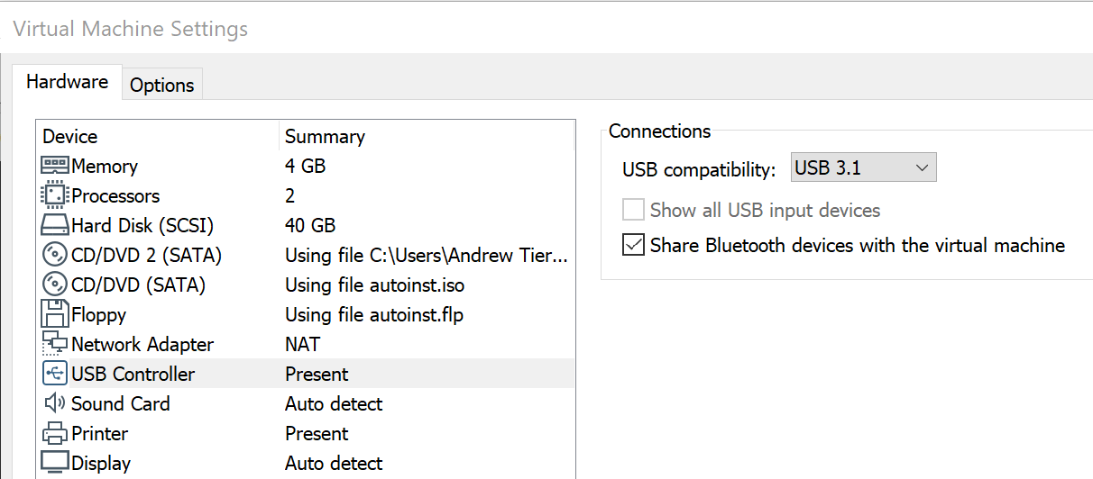
USB 3.0 (or 3.1) support needs to be enable for the VM itself. VM->Settings, then navigate to the USB section and ensure it is set correctly. If you leave this on 1.0, the device will partially enumerate but fail to work correctly – I was once losing random part of packets due to this!
The USB device needs to be passed through to the VM. In VMware Workstation, go to VM->Removable Devices->(name of device) -> Connect (Disconnect from Host). You should get some USB sounds to indicate this happening
Type:
dmesg
And you should see the most recent log entries show the device.
Type:
ifconfig
or
ip
And you should also see the adapter.
Notice the name of the adapter: enx0050b6fff820. The last part is the MAC address of the adapter. In some respects, this is annoying – when you need to type the name of the adapter in (remember – copy and paste!). In other respects, it means you can have multiple adatpers plugged in and not get confused.
If at this stage you are having issues, try power cyling the Ethernet adapter.
Lazy Method of Setting up Connections
I’m fundamentally quite lazy. I’ve found that Ubuntu’s built-in network manager handles the networking setups we need, and does it quickly and efficiently. I’m sure some people won’t be happy with this, but this method works and is easy to remember.
Run:
nm-connection-editor
You should be presented with a window showing two network connections – the VM NAT connection and the new USB Ethernet.
Rather frustratingly, they are not named using MAC address here. Generally, the higher numbered one is the most recently plugged in. Here I select “Wired connection 2” and press the settings (cog) button at the bottom.
Confirm that the “Device” is the same as the MAC address of the adapter.
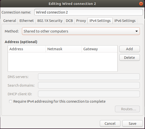
Now click on the “IPv4 Settings” tab. This is where we can choose which of the three options we want.
Receiving an IP address from the device via DHCP
This is the situation if we are connecting to the LAN side of a router, or simply connecting to a network to test.
This is the default “Method” in Ubuntu – “Automatic (DHCP)”. Change or set it to this.
Ensure that there are no “Addresses” listed below – if there are, delete them.
Setting a manual static IP address to communicate with the device
This will often be used when the device under test already has a static IP address. This is common on DVRs and ICS equipment. It is also used when devices enter recovery mode – a lot of routers will take a manual IP of 192.168.x.1, and you need to manually set yourself to 192.168.x.2 or similar to communicate.
Change the “Method” to “Manual”.
Press “Add” next to the addresses. Add the address. The netmask should automatcially populate – generally a 24 subnet will work for IoT. Unless you want to try and route traffic out, leave the gateway blank.
Offering an IP address to the device via DHCP
Most consumer IoT devices will connect out, and assume that they will receive an IP address via DHCP. We want to act as a router for this traffic, allowing us to intercept and tamper with any communications from the device.
Ubuntu can natively do this. Set the “Method” to “Share to other computers”.
Ensure that there are no “Addresses” listed below – if there are, delete them.
That’s it. Your machine will assume the IP address of 10.42.0.1, offer IPs to connecting devices, and route traffic. Simple.
For all methods
Press “Save”. You don’t need to quit out of the list of connections if you don’t want to.
If you have changed from one connection to another, then you will need to drop the connection and bring it back up. There are two ways I do this.
You can simply unplug the network connection, wait 10 seconds, and plug it back in.
Remember that not all IoT devices will request a new DHCP lease if the connection drops – some only do this at startup. We will look at working with Wireshark analyse traffic in a later post to diagnose issues.
In the last post, we setup an Ubuntu 18.04 system for hardware hacking, and used the built-in package manager to install some software we will use.
There are several tools that are better to be installed from source, for a few reasons:
They will be as up-to-date as possible
You can modify them and rebuild them if need be.
Organisation
I tend to keep all of my tools in a subdirectory called “tools”. Not everything is installed into the path, and this helps keep everything neat.
Binwalk
Binwalk is a tool used to examine embedded filesystems and extract them for analysis. The one installed using the package manager in Ubuntu and Kali is out-of-date and missing dependencies that are essential. Crucially, it will not unpack JFFS2 filesystems, which are incredibly common.
The deps.sh script will install the packages required, downloads some repositories, build and install them. This is around 350MByte of downloads, so be prepared to wait a bit.
Answer “Yes” to Ubuntu 18 being detected.
Finally run:
sudo python3 setup.py install
Binwalk should now be installed in the path.
Flashrom
Flashrom is a tool used to interact with SPI flash chips. You can use many USB adapters like the CH431A and FT2232H, or a single-board computer (SBC) like the Raspberry Pi or Beaglebone Black.
Note that if you are going to use an ARM-based SBC, you should compile the tool on the device rather than try and cross-compile in on your Intel machine.
I often find that I need to tweak how Flashrom interacts with chips, especially with the proliferation of cloned devices that misreport JEDEC IDs.
Installation is easy:
sudo apt install build-essential libpci-dev libusb-dev libusb-1.0-0-dev libftdi-dev linux-headers-generic
git clone https://github.com/flashrom/flashrom
cd flashrom
make
sudo make install
That should be it!
OpenOCD
OpenOCD is used to interact with devices using JTAG and SWD. Packaged versions tend to be old and not support all the tools.
sudo apt install libusb-1.0-0-dev libhidapi-dev libhidapi-libusb0 libftdi-dev libtool automake pkg-config
git clone --recursive https://github.com/ntfreak/openocd
cd openocd
./bootstrap
./configure
make
sudo make install
ST-Link
Although we can do nearly everything we need to with STM32 processors using OpenOCD, some scripts and tutorials use ST-Link instead.
sudo apt install make cmake libusb-1.0-0-dev gcc build-essential
git clone https://github.com/stlink-org/stlink
cd stlink
cmake .
make
sudo make install
sudo ldconfig
That last step is just to reload the shared libraries, as the make install does not do it.
We need access to Linux tools to be able to analyser firmware and work with hardware. Some of these tools are already in Kali Linux, but many are absent or out-of-date. Because of this, I prefer using Ubuntu. Ideally, we would be using the latest version (20.04), but binwalk is not supported yet.
To VM or not VM
I generally prefer working inside a virtual machine. Being able to quickly reinstall the OS and take snapshots are huge advantages.
However, you’ll need to accept some issues. USB passthrough is not perfect. You’ll get very used to power cycling USB devices to get them to work correctly. I still can’t get full USB3.0 speed on a passthrough port, hence things like the Saleae Logic get used with my host OS.
Main machine or not?
When you are working with hardware, there is always the chance that you damage your machine. This could range from breaking one USB port to wiping out the entire machine. This said, for work on low-voltage devices, I have not had anything worse than a broken USB port.
If you are careless or your main machine is extremely high value, consider using a secondary machine.
USB isolators are available, but they are not affordable for USB3.0.
If we need genuine isolation (e.g. working on mains equipment), a Raspberry Pi and a network connection are a an effective way of keeping safe. Do not work on mains equipment without suitable training.
VM Software
I personally use VMWare Workstation. It mostly works, though you do need to pay.
I have had mixed experiences with VirtualBox, often finding USB performance abysmal. Ensure you install the VirtualBox Extension Pack to get USB 3.0 support.
I have not used Parallels on OSX enough to say much.
VM Settings
I would suggest:
4-8GB of RAM
40-80GB of disk space – this might seem excessive, but toolchains and firmware unpacking quickly eat it
Enable USB 3.0 or 3.1 in the settings – both VMWare and VirtualBox simply fail to work with USB 3.0 devices otherwise
Allow a means of Internet access, most likely NAT – this is for software updates
Getting up and running
You will likely get prompted to upgrade to 20.04 LTS. Decline this.
First, update and upgrade the system.
sudo apt update && sudo apt upgrade
Next, we want to install some tools that help us build software for the machine we are working on.
We can use the U-boot console to dump the data out over serial, and rebuild it into a binary file!
Getting to the U-boot console
You want to connect up a serial adapter, start your terminal emulator (minicom) and watch the screen as the device boots. It’s highly likely you will see a message:
Hit any key to stop autoboot:
There will normally also be a countdown timer for a few seconds. This is U-boot prompting to see if you want to go into the U-boot console. Reboot, and press a key when prompted!
We are now at the U-boot console. The “hisilicon” prompt is because this is a Hisilicon SoC using their version of U-boot.
In a later post we will look at ways of getting into the U-boot even when there is no obvious key sequence, by glitching one of the SPI flash signals.
Supported Commands
Type help to see what commands are supported.
The number of commands supported varies from device to device, but most low-cost DVRs will have a fairly comprehensive list. Unfortunately (for us), U-boot is mostly concerned with copying data onto the SPI flash, whereas we want to copy data from the SPI flash. The USB commands are not of help.
Frequently a protocol called TFTP is supported – Trivial File Transfer Protocol. On most DVRs this allows data to be uploaded and downloaded. Other embedded devices vary; it’s common to find U-boot only allows data to be download to the device.
There is also a command md – memory display, which we can use to read the memory on the device out over serial.
Let’s look at both methods.
Dumping Memory over TFTP
TFTP is Trivial FTP, a very simple file transfer protocol that U-boot often integrates. We can use this to copy data off the device.
Setting up a TFTP server
In Ubuntu 18.04 and 20.04, the package tftpd-hpa sets up a TFTP server:
sudo apt install tftpd-hpa
That’s it. Files that are received by it will be stored by default in /srv/tftp.
Setting your IP address
U-boot stores settings in something called “environment variables”. If you run
printenv
These will be displayed.
You are looking for ipaddr (the DVR’s IP) and serverip (the IP of the TFTP server). These will generally have default values. You can either change the IP of the machine hosting the server, or you can modify the environment variables. To change both, run:
setenv ipaddr 10.42.0.2
setenv serverip 10.42.0.1
Copy the flash to RAM
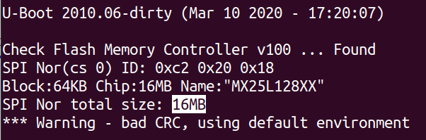
This device has a 16MByte SPI flash chip. You can look up the size using the part number from the board, or just read it from the boot log.
This means we want to read back 0x1000000 bytes. SPI flash is not directly memory mapped on Hisilicon DVRs, which means we can’t directly access it. We need to copy it into RAM first.
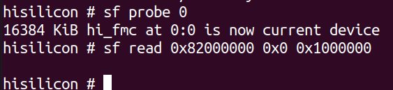
First we need to initialise the flash:
sf probe 0
Now we need to copy the flash into RAM. A suitable address in RAM is nearly always 0x82000000. This command copies 0x1000000 bytes from address 0x0 of the flash into RAM.
sf read 0x82000000 0x0 0x1000000
Copy out with tftp
A quirk of tftp is that you can’t, by default, create files on the server. The easiest way to resolve this is to create an empty file on the server, and let it be overwritten.
cd /srv/tftp
sudo touch firmware.bin
sudo chmod 666 firmware.bin
Note the file has 0 size and is read/write by everyone.
Then, back in the uboot prompt, we run:
tftp 0x82000000 firmware.bin 0x1000000
And now, heading back to the server – we will have the full flash firmware. Simple!
Dumping Memory over Serial
We can use memory display to show us the contents of flash memory.
If you type the follwing command you with get 0x10 (16) bytes of memory from address 0x0.
md.b 0 10
How do we leverage this to extract the flash?
Capture to file
You want to store the output to a file. In minicom, you use:
Ctrl-A L
And choose a filename.
Now we need to dump the RAM:
md.b 0x82000000 0x1000000
This will take some time. Why? Each row is 80 characters long – 80 bytes – and only contains 16 bytes of data. That means for our 16Mbyte flash memory, we need to transfer 80Mbytes over a serial connection! At 115200bps (where each byte takes 10 bits including start and stop bits), that’s just over 2 hours!
This might seem like a long time, but given how safe serial connections are, and how ubiquitous U-boot is, it’s a highly effective mechanism for smaller SPI flash memories. It’s clearly not workable for the 32GByte+ eMMC found in some devices though – that would take months!
Once this is done, close the capture file using:
Ctrl-A L
Trimming the file
Use a text editor to trim anything before and after the memory dump output itself.
Post-processing the file
We’ll use a tool called uboot-mdb-dump to allow us to convert the verbose md output into a binary.
We should now have an image of the entire flash, which can be carved up into partitions (details in a later post) or extracted with binwalk.
Unfortunately, serial extraction like this is prone to errors which this tool might not be able to parse. You can generally edit the file manually, maybe using specific md.b commands to correct damaged areas.
Much more advanced work can be carried out with an impressive tool called Depth Charge , which we will cover in another post. The method here just shows the basic process.
Conclusion
That’s another two methods to get firmware from a device. The first is fast, the second slow. The more tools you have in your arsenal to do this, the more effective you will become.
You’ve managed to get a serial console or telnet shell onto a device, but this can be very limiting. You may not have tools like find, grep and strings. Watchdog timers could reset the device. There may only be a very limited amount of storage space. So how do we copy the firmware off a device like a DVR when we don’t have FTP or SSH available?
If you have a USB socket, the quickest solution is to use a USB memory stick.
Suitable USB memory sticks
I’ve found a lot of DVRs dislike USB3 memory sticks. They should fall back to USB2, but this doesn’t always work. Personally, I really like the Sandisk Cruzer Blade drives, which come in packs of 3 for less than £10.
Size is largely irrelevant. The flash is going to be 16Mbytes or so, and the unpacked filesystem less than 512Mbytes. 8GB or 16GB memory sticks are fine.
The drive needs to be formatted in something that the DVR will support. Generally, FAT is the lowest common denominator. Don’t assume EXT2/3/4 or similar – many DVRs have custom file systems for the hard drives.
Getting a shell
We already have a shell via serial onto the Zosi DVR, as root. Telnet, command injection, a dodgy limited reverse shell – whatever. We want to get the files and firmware off.
We could maybe come up with some xmodem type transfer over serial, but it’s going to be painfully slow.
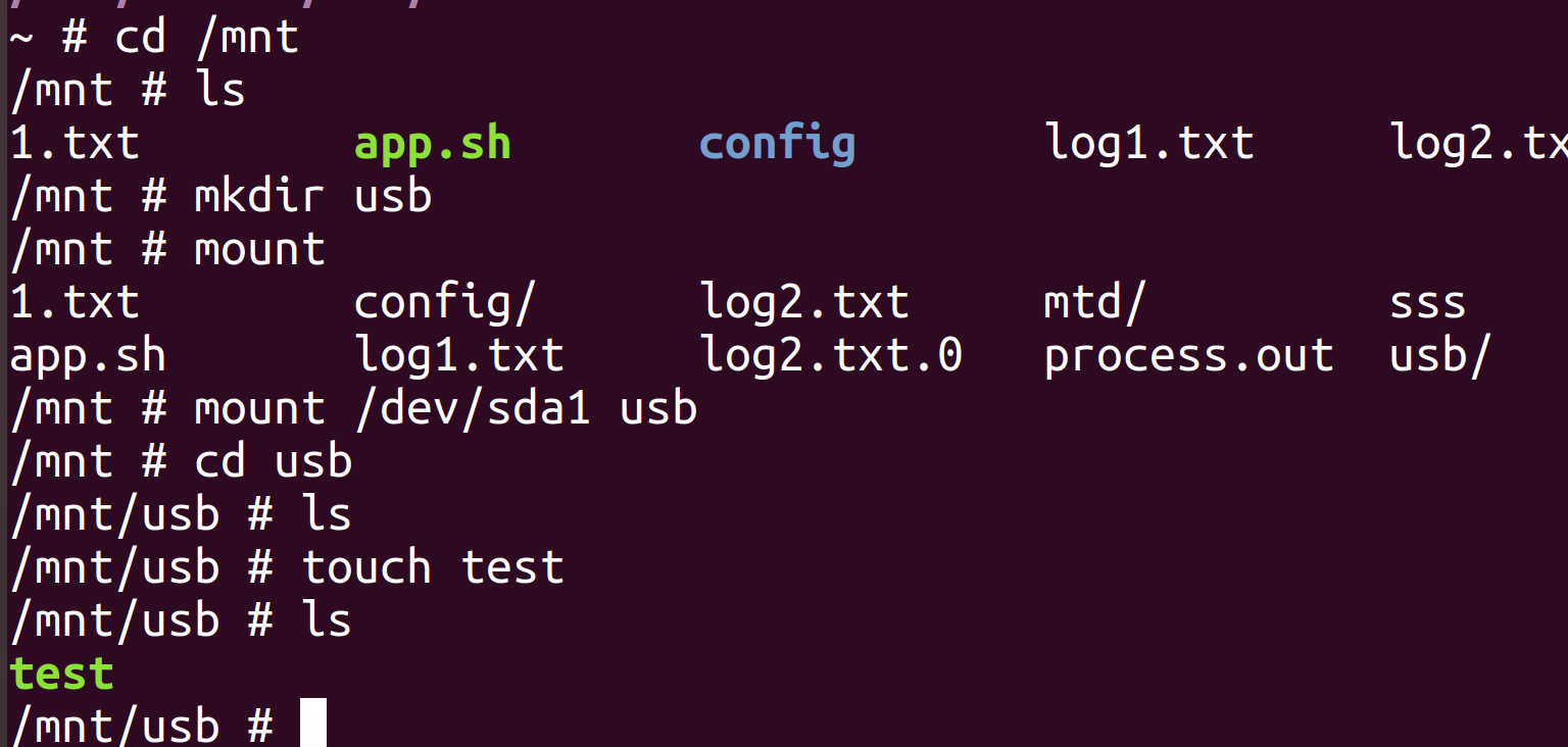
Mounting the USB memory stick
Put the USB memory stick into the DVR. Next, on the device, try running “dmesg”. This should show you if the stick has been seen.
Sometimes, dmesg does not exist. If you have a serial console, these messages may just be dumped out anyway.
Otherwise, you can check /dev/sd* for devices:
Now you want to mount the drive. The following steps are needed:
Create an empty directory to mount the drive (/mnt/usb in this case)
Mount the /dev/sd*1 drive that showed up before
Go into the directory, and test that a file can be written (I used touch)
Copying Firmware
There are different levels at which we can copy the firmware off:
The files inside the filesystem
The raw flash memory
Both are useful, but the files tend to be lower effort.
File copy
There are some challenges here. The USB memory stick is FAT formatted and will not support all the Linux features like symbolic links. We also have limited tools on the device itself to help us here.
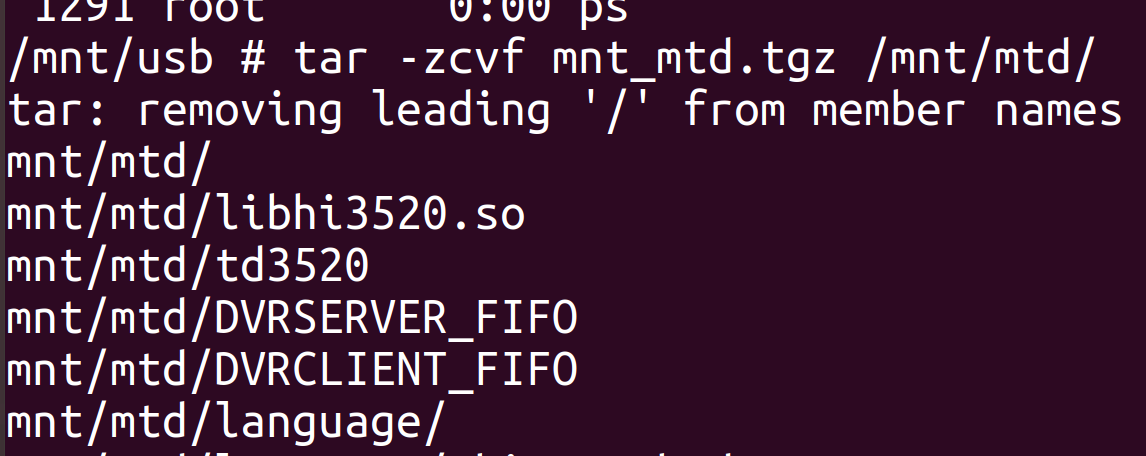
I tend to target individual directories. In this case, the /mnt/mtd/ directory is most interesting – it appears to contain the settings and application.
Most DVRs will support tar, but only the limited busybox version. The following command will put the entire /mnt/mtd into mnt_mtd.tgz in the current directory, which is the USB memory stick we mounted.
tar -zcvf mnt_mtd.tgz /mnt/mtd
There are more efficient ways to do this if you have full tar, but busybox tar does not support directory exclusion. You can create a list of files and provide that to tar.
Raw Flash Copy
There will be some aspects in the flash that you may not be able to see from the OS level, such as U-boot, the U-boot environment variables, and fallback/factory reset images. We can access these at the raw flash level.
First, determine if you can access the flash by running:
ls /dev/mtd*
MTD is Memory Technology Device. You can’t directly tell how big they are using ls.
You can just copy these directly onto the memory stick using:
cp /dev/mtd0 /mnt/usb/mtd0.bin
However, this one-liner is probably easier:
for f in /dev/mtd?; do cp $f /mnt/usb/${f##*/}.bin; done
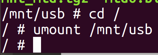
Unmounting
You now need to unmount the disk. Don’t just try pulling it out – it may not have flushed. Leave the directory and run:
umount /mnt/usb
Analysis
You now have the files on a USB stick. You can analyse them at your leisure, with binwalk, emulators, strings, IDA, Ghidra!
Conclusion
This is a quick and easy way to get files and flash images off a device with only serial access. It doesn’t always work, but it often does.
Many embedded Linux devices will have a serial port on them, which can allow us access at either the bootloader or operating system level. This can be a powerful tool to the reverse engineer, allowing recovery of firmware, dynamic analysis, and access to other hardware components.
Interacting with the USB serial adapter
I am using Ubuntu 18.04 LTS as my operating system. Ideally, we should be using 20.04, but some tools that are heavily used in hardware hacking (like Binwalk) do not currently work under 20.04. You can work inside a virtual machine.
Windows is a world of pain; it’s probably tolerable on a Mac but I have not tried.
Connect the USB serial adapter to the machine. In a terminal, run the command “dmesg”. This should show you if the device has been recognised. They mostly show up as /dev/ttyUSB0.
You now want to install minicom. This is a terminal emulator that we will use to connect to the DVR. There are alternatives, but I find minicom is the easiest.
sudo apt install minicom
Next up, we want to run minicom. We need to tell it which device we are interacting with. By default, you need to run minicom as root to access serial devices.
sudo minicom -D /dev/ttyUSB0
You should now get minicom running.
On the USB serial adapter, use a jumper wire to connect RX back onto TX. Why? You always need to test your tools and instruments are working before using them in anger. This should loopback what you send, demonstrating that the adapter can both send and receive.
Trying typing. Nothing will happen – our tools are not working! This is because hardware flow control is on, and we need to turn it off.
Press the following keys:
Ctrl-A Z
(as in Ctrl with A, let go, Z)
This shows you the different commands you can carry out. We want to cOnfigure Minicom – so press O.
Scroll down with the cursor keys to “Serial Port Setup”.
Press enter, then press F to turn OFF hardware flow control. Press enter to leave the menu.
Now scroll down to “Save setting as dfl” (default) – this saves the change so we don’t need to make it again.
Finally, scroll down to “Exit”.
You should now be able to type and see the characters come back! Try disconnecting the wire to confirm that it is being carried that way.
By default, minicom is at 115200bps. Nearly all DVRs seem to use this, but if you do need to change it, press
Ctrl-A P
And then you can use A/B to shift up or down the common baud rates.
To exit minicom, do
Ctrl-A X
Finding the Physical Serial Port
For this particular example, I am looking at a Zosi CCTV NVR/DVR. This has a labelled and obvious serial port on the board. In a previous post, we looked at identifying security-relevant parts of a DVR, including serial ports. In a later post, we will look at using a logic analyser to work out if something is a serial port.
The pitch of this connector is not the typical 2.54mm that we’d find. It’s 2mm. We want to connect to it – so how do we do it?
Get hold of 2mm pitch pin-headers. I recommend that people have a stock of common pitches of pin headers at hand.
Shoe-horn 2.54mm pin-headers onto the board. This sounds awful, but if you chop the plastic separator apart, they fit very well.
Solder wires on. This is the best option, but I’m very lazy and would rather avoid it.
In this particular instance, I am not even going to solder the connections on. Push-fit is good enough for my needs today.
Silence is Golden
Nearly all DVRs have a buzzer on them. It gets annoying very quickly. Plug it with some Blu Tack to reduce the volume, or desolder it.
Yes you could copy my fingerprint
Checking Ground
Even though we have a silkscreen showing one of the pins is ground, we should absolutely confirm this. Whilst it is unlikely to cause serious harm, connecting 12V on the DVR to ground on your laptop could have consequences.
To do this, we use a multimeter in continuity mode. This is normally indicated by the buzzer symbol and sometimes needs a button press from resistance (“SELECT” is common).
Never perform continuity tests on a powered board. The continuity test works by testing for resistance – the meter does this by applying a voltage to the board. It will get very confused if there is already voltage present.
Always confirm the meter is working by touching the probes together first.
Find a known ground. The following are good places to look.
USB connector shields – be warned you might need some pressure to break through oxides or coating/
The outer connection on the barrel jack power connector for most DVRs. This is normally on the side of the black plastic socket.
The middle two pins of a Molex power connector for the hard drives (not present on this DVR board).
The top (-) of the coin cell for the RTC backup battery.
The BNC video connection outers (not present on this DVR board as it uses WiFi cameras).
Screw mounts for the PCB to case often have a grounded ring around them.
Pushing needle probes through the solder mask into a ground pour.
Visual inspection can also show which pin is ground. As can be seen on this DVR, the pin marked UART_GND is connected to a large ground pour around it, whereas the UART_TXD and UART_RXD pins have thin signal traces.
Checking Voltage
Serial ports can work at different voltages. We need to make sure we are using an appropriate USB serial interface for the voltage. In order of descending popularity:
3.3V – this is typical for a DVR
5V – older DVRs may use this
12V – some DVRs use this for interacting with external devices
1.8V – some DVRs with newer chips may use this.
RS232 – this is +/-25V – sticking this into a normal 3.3V USB serial adapter will not be good.
The best tool for checking this is an oscilloscope, but we don’t all have them. So let’s use a multimeter and acknowledge the limitations.
Power the DVR. Immediately measure the voltage between ground and TX and the voltage between ground and RX. Then wait a couple of minutes for it to boot, and measure again.
On this board, with this multimeter I see:
Ground to TX -> 3.29V with some slight fluctuations
Ground to RX – > 2.36V mostly constant
I can be fairly confident that this is 3.3V logic. Let’s talk through some of what we saw there:
The quiescent state for TX on nearly all serial ports is the high state. If we saw 0V most of the time, this assumption would be false.
The TX signal will have data on it as the device boots. It will fluctuate between 0V and 3.3V. A multimeter only shows an average value, and the mechanism by which it averages is fairly arbitrary. We measure the voltage right at the beginning (before serial output) and at the end (generally, the device will go quiet after a while) to avoid this issue.
We measure both TX and RX because we often don’t know which is which at this stage. They are also frequently labelled incorrectly – TX and RX flip depending on which perspective you are looking at it from!
Why is RX at this strange middle ground of 2.36V? It is highly likely that there is no pull-up or pull-down resistor on the board, leaving it “floating” when not connected.
An oscilloscope would let us observe the high and low voltage.
Connecting the USB serial adapter to the DVR
The device is working at 3.3V, so we can use one of the readily available 3.3V USB serial adapter. Any of these will do.
The USB serial adapter will have the pin-out labelled on it. We want GND, RX and TX.
With both the DVR and the USB serial adapter turned off, connect up the three wires. GND always goes to GND. RX on the adapter goes to TX on the DVR, and TX on the adapter goes to RX on the DVR.
I would recommend always using black for ground wires, just to keep things clear.
If you get RX and TX the wrong way round, nothing bad will happen. You just won’t get any output. If this happens, try swapping the wires around.
I used test clips for this particular situation as they were to hand.
Bringing it all together
Connect the USB serial adapter to your machine. Start minicom as we did earlier.
Turn the power onto the DVR. You should see text very quickly! You can capture this into a text file using:
Ctrl-A L
Choose a file name. Press the same key combination to close the file. We’ll use this to recover the firmware in another post.
The first part is the bootloader – U-boot. Considering the DVR was bought in 2020, U-boot from 2010 might be considered out of date.
You can see that the SPI flash chip has been identified as an MX25L128XX. It’s 128Mbits or 16Mbytes in size.
You might then see a prompt saying that you can press a key to stop autoboot. This is a prompt to get into the U-boot console. You might have to hammer a key repeatedly to get into the console. This isn’t the operating system – this is the bootloader before that stage. You can still read and write the flash, which we will use in another post to recover the firmware.
If you don’t go into this console, the device will carry on booting.
Many DVRs stop immediately after U-boot, as the serial console is disabled in the kernel. Not this time. We see normal system logs fly past, and then what looks like logging from the DVR processes:
Don’t make the assumption that you don’t have control when you see this. A process might be outputting to the console, but that doesn’t mean you can’t provide input.
Yep, we are straight in as root, no password. The annoying DVR logging sticks about though – I think it’s actually partially built into the kernel, making it impossible to suppress.
And, with a bit of exploration, we quickly find a file called config.dat in /mnt/mtd/config/ that contains the admin password as plaintext.
Not great for a new DVR!
Conclusion
Hopefully, you have seen how easy it can be to get a serial console on a DVR. In this case, we have full OS-level access.
In the next post, we’ll look at a quick way of recovering files and firmware from a DVR to analyse on our own machines.
DVRs (Digital Video Recorders) are interesting targets for hardware hacking. They are generally powerful Linux machines with multiple network interfaces and have historically been full of vulnerabilities.
Identifying the security-relevant components on a DVR board make it far easier to quickly attack and gain access to the various interfaces: serial ports and SPI flash memory being the most important. We can also quickly isolate areas of the board that are not of interest; power supply, RAM, video ADCs, HDMI etc.
Disassembly and Powering
I would recommend removing the main PCB from the case to make access and inspection easier. Nearly all DVRs run on 12V, with a few running on 48V. Less than 120VDC and 50VAC is classified as SELV (Separated Extra Low Voltage) in the UK and is safe to work on in electrical shock terms. These low-voltages are still capable of causing heat, smoke and fire if shorted.
You do not need to have the hard drives connected when working on the DVRs. For 99% of DVRs, the drives only store footage, no operating system or configuration. Disconnect them, especially if you want to recover footage from them.
For nearly all 12V DVRs, a barrel jack power connector is used.
You can use the provided wall-wart style power supply but be warned that the quality and safety of many is in question. You can use a better quality power supply, but check that:
The voltage matches. This should be a direct match – a 12V power supply for a 12V device.
It can supply enough current. The replacement should be able to supply more current e.g. a 2A supply is suitable to replace a 1A supply. A DVR without drives will generally only consume a fraction of the power needed during normal operation.
The polarity matches. Nearly all DVRs are centre positive. You can check this by looking for the pictogram on the original power supply.
The power supply below is 12V, maximum 2000mA (2A), DC (the straight line above dots) and centre positive.
Personally, I use a bench power supply when working on them, as this allows me to limit the amount of current provided. Simply chop the barrel jack off the end of an existing power supply and use this.
Many DVRs will have a heatsink on the main chip. This can make finding out the part number difficult, or finding out where pins go to. You can often remove it with careful levering. Generally, because we will be running the DVR without video feeds, the chip will not get hot enough to need a heatsink. As a rule of thumb, if you can’t touch the chip for more than a few seconds, it is too hot.
High-level Overview
Many of the low-cost DVRs are based around a Hisilicon chipset. These are large, powerful ARM SoCs (System-on-Chips) containing a wide array of peripherals.
SPI Flash
They tend to use SPI (Serial Peripheral Interface) NOR flash memory for storing the firmware and configuration. These range from 8Mbytes to 64Mbytes in size. This is a particularly convenient flash memory format for the reverse engineer.
Firstly, most of them are packaged in 8-pin SOIC (Small Outline Integrated Circuit). This is a comparatively large package, with the pins being accessible and 1.27mm apart. This makes physical access to the signals easy.
Secondly, the SPI interface is very simple. There are only 4 signal wires:
DI (Data In) or MOSI (Master Out, Slave In)
DO (Data Out) or MISO (Master In, Slave Out)
CS (Chip Select)
CLK (Clock)
As with all interfacing, we will need to find a common ground. Sometimes we also need to provide power as well. Regardless, this is a small number of signals, especially compared to parallel NAND flash which needs more than 14 connections on a finer pitch package.
Thirdly, although SPI only technically allows a single bus master, we can bend the rules and add another master to directly interact with the flash memory.
Fourthly, NOR flash does not suffer from bad blocks as NAND flash does. The data we read out from the flash will be the same as seen on the filesystem. There is no overhead to handle bad blocks.
Serial Ports
The majority of DVRs will have a serial port on them. These are sometimes called UARTS or USARTS (Universal Synchronous Asynchronous Receiver/Transmitter). This will be a conventional asynchronous serial connection with receive (RX), transmit (TX) and ground (GND). This serial console will often allow access to the bootloader, and sometimes access to the Linux console itself.
RAM
Nearly all DVRs copy data from flash into RAM before executing it. This is why the flash is small (~16Mbytes) and the RAM large (>256MBytes). It would be desirable for us to access the RAM to inspect the OS and see any data the device is processing.
Unfortunately, on these devices, the RAM is DDR3 running at 800MHz or above, using a parallel bus. There is simply no low-cost or accessible means to intercept these signals.
JTAG
It is likely that some DVRs have JTAG on them, but I have had very limited success in interacting with a DVR using it. It would allow flash access, RAM access, and the ability to debug.
Typical DVR
This is a Sansco DVR bought from Amazon in 2020. It is representative of a typical DVR.
In red is the large Hisilicon Hi3520 SoC. I have removed the heatsink, but not the compound holding it on. In blue is the DDR3 RAM. In green is the SPI flash.
Sansco DVR
The PCB will generally be 4 layers or above. This means that there are layers inside the PCB that you cannot easily see. It is possible for these to carry signals across the board. Most interesting signals will be carried on the surface, with the inner layers reserved for power and ground.
All PCBs will have a solder mask, which is the green layer. This is used to stop solder sticking to places it shouldn’t be. You can generally see traces through the solder mask, and you can push needle probes through this layer to reach traces below.
Most PCBs will have a silkscreen. These are the white letters showing names of components and connectors. The most common letters are:
R – resistor
C – capacitor
L – inductor
CN – connector
U – semiconductor
T – transistor
X – crystal
Looking at the Hisilicon SoC in more detail, you will note it has pins all around the outside. This is an LQFP package. The signals being accessible around the edge can be extremely helpful when reverse engineering. It has a very fine pitch of 0.4mm – you will struggle to clip or solder to these.
Some DVRs have chips in BGA packages, with the connections under the chip. This can slow down reverse engineering.
To identify pin 1 on a chip such as this, you tend to look for a dot or dimple. You’ll see there are three on this chip – generally, it’s the smallest and deepest one. You can also see a “• 1” marked on the white silkscreen. The logo and text orientation to not have any relevance as to pin 1 – it’s arbitrary.
Next up is the RAM. This will nearly always be in BGA package, physically close to the SoC. There will be a lot of parallel traces going to it, some of which may be “squiggly”. These are called matched-length traces, and are often indicative of RAM. They have to be the same length to ensure that the extremely fast signals arrive at the chip at exactly the same time.
DDR3 RAM
Onto the SPI flash. This will nearly always be in 8 or 16-pin SOIC packages. Part numbers with “25” in them are common, as are binary multiples such as 16, 32, 64, 128, 256 (indicating the size). Manufacturers include Winbond, Spansion, Macronix, and Atmel. The pin-out of the chips is nearly always the same, and the protocol used to communicate with them is very similar. In this case, we have a device made by a smaller company I don’t recognise.
We actually determined that this was the SPI flash partially by elimination. The brand (XMD? XMC?) and part number did not yield good results on google.
The only other 8-pin chips were a small memory (setting and MAC address) and switch-mode power supply ICs. The small memory is an FM24C08D – a 2-wire (or I2C) serial EEPROM, only 8kbytes in size. Not big enough for the firmware!
Serial EEPROM
Nearly all DVRs will have an RTC on them. This is to keep accurate track of the time, even if the power is cycled. We can quickly identify if one is present by two components.
First, they will have a coin cell to provide battery power. Some use different forms, but this is by far the most common.
Coin cell
Second, they will have a 32.768kHz crystal. Why this odd frequency? If you divide it by 2^15, you get one pulse per second – ideal for timekeeping! These crystals are nearly always small cylindrical silver cans.
There will be other crystals to drive other chips – normally the SoC has one at 24MHz, in an oval-shaped can.
32.768kHz crystal at top and 24MHz at bottom.
Next up is the video ADC (Analog to Digital Converter) or RX (Receiver). There will be one or more of these chips on the board, taking analog video and digitising it. There tends to be one chip for every 4 channels. This is in a QFN (Quad Flat No-leads) package, which means you can just about access the signals around the edge. This part of the board is generally not of security interest though.
Video RX or ADC
Nearly all DVRs will have an Ethernet port. Ethernet is isolated, using a small set of transformers. Often there is a large package near to the port containing these transformers. It is not a chip and is not interesting in security terms.
Ethernet jack and magnetics
The area near to the power input will be the power supply. There will generally be a switch-mode power supply to drop the voltage down from 12V to 5V, then linear regulators for the 3.3V for the SoC. Again, this has little security relevance to us.
Power supply area
We can quickly isolate power supply areas by looking for certain components. 4-pin packages with one very large tab are normally linear regulators. The large tab allows heat to be conducted onto the PCB to keep it cool.
Regulator
Large cylindrical capacitors are called electrolytics, and are power reserves, used for smoothing.
Electrolytic capacitor
Finally, small coils of wire are inductors, very common in switch-mode power supplies. They will be marked with an “L”
Inductor
Finding serial ports is key. I’ve found that for most DVRs, this will be 3 pin – GND, RX and TX. There is also sometimes a voltage supply as well.
On this DVR it was a 3-pin connector. You can easily make out the ground – it’s the left, pin, connected to the large “ground pour” on the PCB. The other two pins have very fine traces, leading away – likely signals.
Find all the suitable candidates for serial ports when performing an overview of the board. We’ll look into working out if they are serial and how to connect in a later post.
Serial port
Conclusion
I hope that’s helped in understanding the major components on a DVR. This can be applied to most small embedded devices, but many routers and other IoT now use different forms of flash memory such as eMMC.
If you are starting out in hardware hacking, then you need a toolkit. For some aspects of this, it’s worth spending good money for a quality tool. For other parts, low-cost alternatives can be better.
This post details what I would consider the absolute starting point.
Multimeter
Your multimeter will be one of your most commonly used tools. Most of the time, you will be in continuity or voltage mode. Sometimes you will be measuring resistance. Rarely will you measure current. Frequency, capacitance, and duty cycle are virtually useless for embedded systems.
You want a responsive and loud continuity buzzer – ideally a “latching” one. This is virtually impossible to determine from specifications – YouTube reviews will often cover this.
From a usability perspective, it is desirable that the meter has a dedicated continuity mode or stays in continuity mode through power-off. Many meters require a button-press to go from resistance to continuity mode, which leads to using the meter in the wrong mode.
An auto-ranging meter generally makes work quicker, as you don’t need to change the range. Be warned though, some cheap meters have incredibly slow auto-ranging, which becomes frustrating quickly.
Separate current and voltage terminals are essential. Some meters share a single terminal for both, with the function being changed by a selector dial. This changes the meter from high-impedance (>1MOhm) to low-impedance (<1Ohm), which can lead to mistakenly shorting out power supplies.
In terms of resolution, accuracy, and precision, we generally aren’t bothered as long as the meter isn’t truly shocking. Anything with less than 4000 counts may not be adequate.
Multimeters have varying levels of safety. Unless you know the meter is a genuine one from a reputable manufacturer (Fluke, Brymen, Agilent/Keysight, Amprobe etc.), be extremely cautious using them on mains voltages or in high-current situations.
This isn’t the place to be discussing the difference between CAT II/III/IV meters, but if you are working on mains installations, I would strongly recommend following the route electricians have: two pole testers that simply cannot measure current.
My recommendation is the Brymen BM235. This is a reliable and accurate meter that does nearly everything you will need. If you think you will be in this game for the long run, I’d really recommend getting a decent meter.
Multimeter Probes
The probes that come with your meter will likely have large, relatively blunt tips. In my opinion, a major upgrade is switching to needle probes.
There are very fine probes which are as sharp as a needle. They make it easy to probe individual pins on fine-pitch semiconductor packages. Because they are so sharp, they allow you to break through oxides, conformal coating, and solder masks easily.
The image below shows a 0.5mm pencil, a needle probe, and the sharpest normal multimeter probe I have. There is a very clear difference.
I recommended Pomona 6275 for this. These ones come with stainless steel tips, which are very sharp and robust, but at the cost of slightly increased contact resistance.
Be warned, this can only carry 3A at 60V. They are not suitable outside electronics.
USB-to-serial adapters
Connecting to serial consoles is extremely common. I’m a big fan of cheaper USB-to-serial adapters based on the CP2102/4, FT232R, and PL2303. There’s very little to differentiate between them in functionality. Some support 5V and 3.3V operation, but nearly all of the time 3.3V will be what you need.
These are the kind of devices that you lose, get borrowed, or break. You can order packs of 5 from Amazon for around £10-12. However, you can also buy them for around $0.70 from Aliexpress, which works out to around 70p each with postage.
USB Ethernet adapter
You are likely going to end up working with Ethernet connected devices, and want to pass traffic through to a virtual machine. Rather than bridge to the physical adapter, I find it is far more versatile to use a USB Ethernet adapter.
I like the Amazon basics ones. They work well, the link and activity lights are exposed, and they have the MAC address printed on the back of them.
It is also worth sourcing a USB 2.0 Ethernet adapter – these have wider support on older OS and systems. You would be surprised how many devices offer up an unfiltered network interface when you plug one in! I have several of the Plugable ones from Amazon that have lasted well.
USB WiFi adapter
For WiFi connected devices, you will want to make a hotspot on your machine. For this, you need a USB WiFi adapter that can act as an access point.
I have a stock of TP-Link TL-WN722N, but only the V1 is suitable for this. The readily available Alfa devices are suitable as well.
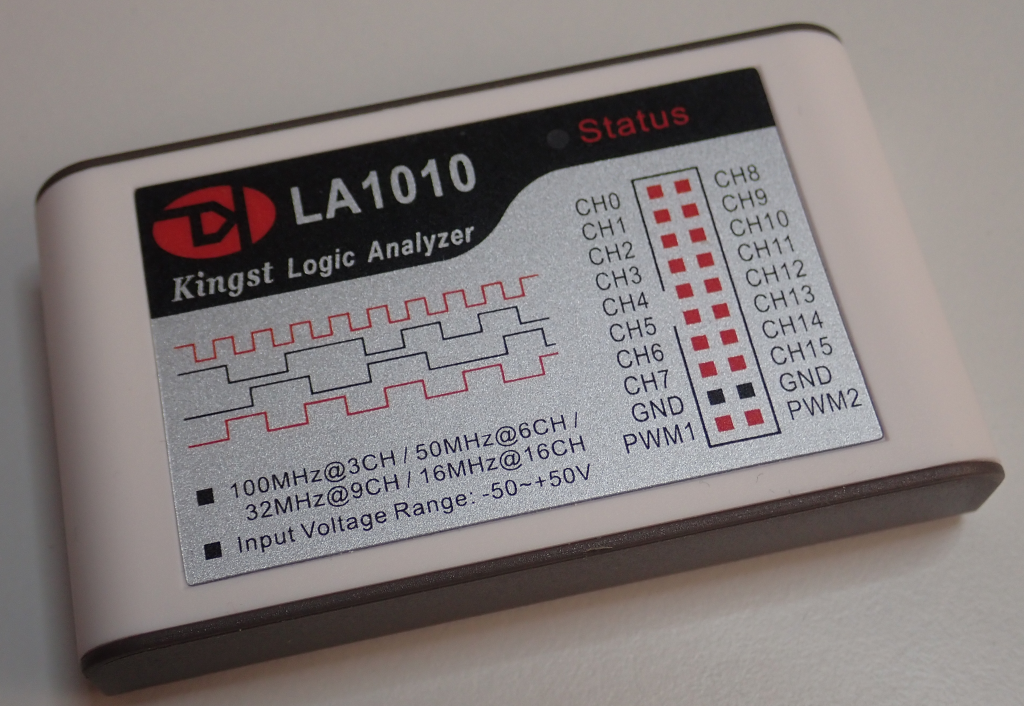
USB Logic analyser
A logic analyser allows you to monitor multiple digital signals at the same time. There are a lot of options on the market here.
Generally, when reverse engineering, you are looking at signals over a long period of time. SPI, serial, I2C. You favour sample length, convenience and the ability to quickly export data to files for post-processing.
It’s for this reason that I prefer USB logic analysers. They facilitate reverse engineering. Dedicated instruments with screens are more useful for timing issues and lots of parallel channels.
Professionally, we all use Saleae Logic Pro 16. They are, however, expensive. The analog inputs, whilst helpful from time-to-time, are not strictly required.
At the opposite end of the market are the low-cost Hobby Components devices. 8 channels are adequate for a lot of work, but the 24MHz sample rate can be limiting when dealing with faster signals. They often struggle to get even 10MHz on many laptops. Adequate for serial ports, but not SPI.
With all of these USB devices, you are going to want a USB hub. Not only do these give you more ports, but they provide a degree of isolation between your laptop and the device you are working on.
The Sabrent switched hub from Amazon is great. This has individual power switches per-port, allowing you to quickly power cycle devices. If you have ever worked with USB in a Linux VM, you will quickly see why this is desirable!
Making Connections
The part missing from this post is making connections to devices. They don’t have pin headers fitted all of the time. That’s coming up.
When working with IoT and embedded systems, brute-force password guessing attacks are an effective tool to gain access. Over the years, I’ve learned some tips and tricks to make these attacks more effective.
What is brute forcing?
Very simply, it’s guessing passwords so that you can find a valid one and login to the device.
It’s often referred to as “password cracking”.
Online vs offline brute forcing
There are two forms of brute-force attack.
One is online. This means you are actively trying to login to the device using the web interface, telnet, SSH, or local console. This has disadvantages. It’s generally quite slow (less than 10 attempts per second, sometimes much slower) and account lockout is a challenge.
The other is offline. This is when you have the hash of a password and can guess passwords on an entirely separate machine. This has advantages. For many types of hash, hundreds of thousands of guesses can be performed each second. But, you need to have the hash in the first place.
(you can read a bit about hashes in an earlier post here)
If I have the device in front of me, and I can risk destroying it, I will generally obtain the hash and perform an offline attack. This isn’t always appropriate though – sometimes devices are too expensive or you cannot risk breaking it.
Sometimes the device has strong physical protections that make obtaining hashes difficult.
Often, an online attack can be setup and carried out in seconds – all you need is network access and a list of passwords. It’s often wise to try this first.
Do I need the password?
If your goal is to gain access to a device in front of you, make sure you have considered other paths.
Devices frequently have vulnerabilities allowing bypass of passwords. Command injection via web interfaces is still very common.
If you can modify the firmware, consider running an unauthenticated telnet shell. Or replace the password hash with one of your own, avoiding the existing password entirely.
What is the goal of getting the password?
With physical access to a device, time, and some skill, it is nearly always possible to login to a device without knowing any passwords.
So why do we want to find out the password?
Firstly, it’s very common to find hardcoded or default passwords on embedded systems. If you can find the password from one device, you can use it on many others. I call these BORE attacks – Break Once, Run Everywhere. The password has much higher value than just the device in front of you.
Secondly, you can perform a high-risk attack against a device on the bench, obtain a password, and then use that password in the real-world. This was what we did on an oil rig, where an attack was developed against a Siemens switch in the lab, and then the attack used on the rig itself.
Thirdly, it’s often possible to quickly and easily obtain a password hash from one device using something like the Cisco Password Recovery mode. You can quickly reset a Cisco switch on an non-critical, physically exposed switch, brute force the password, and then find that same password is in use on the core network.
How much effort are you willing to expend?
Obviously, the longer you spend guessing passwords, the more passwords you can guess.
Online brute force attacks are extremely rate-limited. The workload can be divided up by attacking multiple devices, but if you can obtain multiple devices, why not get the hashes from one of them and move to an offline brute force attack?
Offline brute force attacks cost in processor time. The more computing power and time spent, the more attempts you can make. You can literally throw processor time (and hence money) at the problem!
Depending on the value of the password, you may be willing to spend different amounts. A hardcoded root password for an IoT lightbulb behind NAT has a lot less value than the root password on a maritime satellite router with Internet exposed SSH!
Online attacks
There are three common network services which allow online brute force attacks to be carried out: Web interfaces, telnet and SSH.
A tool called hydra comes in very useful here. It handles these protocols and many more.
SSH is the easiest to deal with. Nearly all devices have a standard response, and the protocol feeds back if you have authenticated successfully or not.
Telnet is a bit awkward. The password prompt, and the feedback you get if you successfully login varies from device to device. Often you need to write scripts to do this properly. Always make sure you catch the success message properly – I once left a script running against a device for an entire weekend and it had found the password in less than 10 minutes.
Web interfaces can be easy sometimes, and incredibly challenging at others. The easiest are ones using HTTP Basic or Digest authentication – this is when you get the pop-up password Window in your browser. This can be easily attacked. Web forms take more effort – generally you need to intercept traffic and work out how the password is being sent. Some devices use JavaScript and other complex authentication flows that take significant effort to reverse engineer and replicate. An intercepting proxy such as Burp or Zap can be of use here.
If the device has account lockout, preventing you trying more than a few passwords, it is always worth checking that this persists through a device reset. It is very common for devices like DVRs to lockout for 15 minutes after 5 wrong guesses, but if you restart the device, the lockout has gone. A USB or WiFi-connected socket can be scripted to restart the device automatically.
Just be warned: a lot of ICS equipment responds badly to brute force attacks. Lockups and restarts are common, and I’ve even caused the relay output on one device to change state.
Cracking rigs
Calculating password hashes requires processor power. The first common password cracking tool, John the Ripper, made use of the main CPU in a machine.
It turns out that graphics cards are far more efficient at calculating most types of hash. Another password cracking tool, hashcat, became available, making use of multiple graphics cards. This hugely accelerated the rate at which passwords could be guessed, but required significant investment in hardware, and ongoing electricity and cooling costs.
Then cloud computing happened. It’s now possible to rent machines with graphics cards in them and perform password cracking in the cloud. You can spin up as many machines as required and use tools to split the workload amongst them. This can be very helpful when you do not know how often you need to perform password brute force attacks.
Picking your passwords
There are several common methods to generate lists of passwords to attack devices.
A dictionary attack takes a pre-generated list of words and tries them all. There are many readily available password dictionaries of varying quality, some contain millions of passwords. These dictionaries can be very effective against large sets of hashes, such as those from a website breach or Windows Active Directory.
Building your own dictionary based on the vendor and product can help. The tool CeWL can spider a website and return a list of words for use in password attacks.
A brute force or incremental attack tries all possible combinations. With these attacks, the character set used and the length of the password become important. The more characters tried and the longer the password, the larger the search space becomes and the longer an exhaustive search will take.
Most passwords consist of upper and lower case letters, numbers, and possibly symbols. The more of these that are used, the larger the search space.
26 lower case
26 upper case
10 numbers
10 common symbols
20 relatively common symbols
So, if the password contains lower/upper/number/common symbols, there are 72 possible characters.
If the password is 8 characters long, this results in 72^8 possible passwords. This is 7.22e14 – a very large number.
It’s at this point that we need to consider how quickly we can guess passwords. This is highly dependent on the hash algorithm used. For a typical high-end hashcat rig, the following are approximate rates.
Algorithm
Guesses per second
MD5
200,000,000,000
descrypt
7,290,000,000
md5crypt
80,000,000
bcrypt
105,000
There is a huge variation here. This can dictate what kind of attack is viable. With our 72^8 attack above, the length of time for an exhaustive search for the above algorithms is as follows:
Algorithm
Time
MD5
1 hour
descrypt
1 day
md5crypt
105 days
bcrypt
218 years
On average, the password will be found in half that time. 30 minutes vs over 100 years! It’s clear that brute-force is not a viable attack for bcrypt. For md5crypt, as long as you know the password is in that space, 105 days may be a reasonable expense depending on the value of that password.
This is also why it is key to understand the password complexity. descrypt only hashes the first 8 characters of the password. Combined with the speed at which we can guess, it makes exhaustive searches possible.
Let’s see what changing the character set does to the times if md5crypt is used.
Character set
Options
Time
lower/upper
52
7 days
lower/upper/number
62
32 days
lower/upper/number/common symbol
72
105 days
the kitchen sink
92
2 years
Again, there is huge variation. 7 days is likely viable, but it is a big risk assuming that no number of symbols were used. Equally, 2 years is a long time to spend to find a password and there is still a chance they used some quirky symbol and you never find the password.
Always keep in mind the language of the developers. It’s rare to find umlauts in US and UK passwords, but don’t assume that for a product developed in Germany.
And what about the password length changing? Again, with md5crypt and 72 characters.
Password length
Time
8
105 days
10
1500 years
12
8 million years
14
Yeah.
It becomes obvious that if the password is longer, plain brute force attacks quickly become useless.
Hashcat also has other modes of operation that are more refined.
Mask attack mode takes a pattern and then applies a brute force attack within those limits. It’s very common to find that certain vendors, companies and users follow certain patterns, such as using iwhd7262, baid8621. Mask attack mode can be very helpful here.
This is also a good mode for things like passwords based on serial numbers and MAC addresses.
One of the most powerful modes is the rules mode. This takes a series of different rules and applies them to a list of passwords. This can be things like changing the case, appending numbers, swapping letter for numbers (i->1 a->4). There are complex sets of rules published, all of which can be very effective.
Open Source Intelligence
It is always worthwhile researching the vendor and their other products. The one you are looking at may not have a published password, but other products could, and they may follow a pattern.
In one instance, Samsung had a hardcoded root password across many of their cameras. Nearly all of their cameras used bcrypt, making an exhaustive search unlikely to succeed as it is so slow. However, one model of camera was using descrypt. An 8 character exhaustive search was carried out, yielding a complex (but short) password. This was found to be the same password on the device using bcrypt. With bcrypt, we would never have found the password.
Find it in other forms
Never assume that the password is only stored as a single hash on the device. It’s very common to find it hashed using different algorithms or stored in plaintext.
One device we looked at used Webmin for the web interface. This stored the passwords as descrypt, so an exhaustive 8 character search was started. This quickly gave up the passwords for all accounts.
The main Linux login used bcrypt though. Exactly the same accounts existed in Webmin as for the OS. Taking a stab in the dark, we assumed that the passwords were the same for both hashes, just truncated for the descrypt one. We knew the format and character set, so launched a hybrid attack using the first part which we already knew and brute force against the bit that we didn’t. We would never have found the passwords without the first 8 characters being known.
Passwords often get stored in plaintext. Common locations for this are WiFi hotspot configurations in hostapd.conf (the WiFi password is often the same as the OS login) and setup/factory reset scripts.
Conclusion
Hopefully the above tips and tricks have helped you understand password brute force attacks so that you can effectively use them against devices.
Cryptography is a complex subject. There are many subtle issues that can be introduced if you don’t know what you are doing.
There is a common mantra: “don’t roll your own crypto”. This is because both inexperienced and experienced developers frequently build cryptographic systems that are insecure.
However, there has to be a line – when does it start becoming “rolling your own”? Particularly in embedded systems, there are times when custom protocols need to be used, and developers stray into the dangerous area of cryptography.
One of the most common mistakes we have seen is the use of unauthenticated encryption.
What is encryption?
Encryption is encoding a plaintext into a ciphertext using a key, with the goal of keeping the plaintext confidential.
Only someone with the correct key should be able to decrypt the ciphertext and turn it back into plaintext.
Encryption provides confidentiality. It stops someone working out what the message is.
So what’s the issue?
An attacker can modify the ciphertext and cause the plaintext to change. There is no inherent means in encryption to detect this change.
Encryption does not provide authenticity. You cannot check that the message is genuine and has not been tampered with.
What can an attacker do with this?
I’m going to describe one attack against unauthenticated encryption.
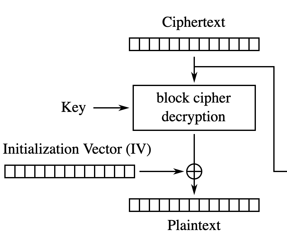
Many encryption algorithms only operate on fixed-size blocks of data – they are called block ciphers. To encrypt longer lengths of data, a mode of operation is used to apply the block cipher repeatedly.
One mode of operation is called CBC (Cipher Block Chaining). When encrypting the data, the previous ciphertext block is mixed into the current plaintext block using an operation called “exclusive OR“. This is denoted with the + in a circle in diagrams.
There is also an input called the initialisation vector, or IV. This is a random input to the algorithm, and is intended to ensure that the ciphertext is different, even if the same plaintext is encrypted. This prevents leaking information about the content.
The initialisation vector is transmitted alongside the ciphertext.
Decryption is similar. The previous ciphertext block is exclusive ORed with the output of the block cipher to obtain the plaintext.
Exclusive OR is a deterministic operation. If we look at a single bit, then it operates as follows:
A
B
Output
0
0
0
0
1
1
1
0
1
1
1
0
I always think of this as “if one input is high, invert the other input, otherwise leave it alone”.
The operation is carried out for each bit in a byte.
What this means is that modifying one of the inputs to exclusive OR results in a predictable change to the output. And the operation can be easily reversed.
Let’s look back to how CBC uses this in decryption. In the first block, the IV is exclusive ORed with the output of the block cipher. The IV is transmitted alongside the ciphertext and an attacker can modify both at at will.
We can encrypt the string “A dog’s breakfast” using a key and the initialisation vector of all 0x00 (here on CyberChef).
Key: 0123456789ABCDEF0123456789ABCDEF
IV:  0000000000000000000000000000000
Plaintext: A dog's breakfast
Ciphertext: c7b1d96f0f520f33faaccfdc107f718aafe8892c3a29c76b0732a760a0f54f50
Of course, this can be decrypted (here on CyberChef).
If I change just one byte in the ciphertext, the entire message is corrupted (here on Cyberchef). There’s no way for me to predictably modify this plaintext by changing the ciphertext.
But the attacker also has control over the IV. Let’s set the first byte of the IV to 0xFF (here on CyberChef). Only the first byte of the plaintext has changed!
And it has changed predictably. The capital A (ASCII 0x41) has been exclusive ORed with 0xFF to become 0xBE (which decodes as ¾ although it’s above the normal ASCII range).
This is a very high level of control! The attacker can now modify the plaintext without detection. Let’s try and significantly change the meaning of it.
The original message contained “A dog’s breakfast”. Can we change this canine feast into a feline one?
We exclusive OR the original plaintext with the desired one (here on CyberChef). Notice how the output only has value for the characters we have changed.
Original: A. .d.o.g.'.s. .b.r.e.a.k.f.a.s.t.
Original: 4120646f67277320627265616b66617374
Desired:  A. .c.a.t.'.s. .b.r.e.a.k.f.a.s.t.
Desired:  4120636174277320627265616b66617374
Output:   0000070e13000000000000000000000000
Pop that output in as the IV to the decryption, and we’ve successfully changed the message (here on CyberChef). All of this without even knowing the key.
Key: 0123456789ABCDEF0123456789ABCDEF
IV:  0000070e130000000000000000000000
Ciphertext: c7b1d96f0f520f33faaccfdc107f718aafe8892c3a29c76b0732a760a0f54f50
Plaintext: A cat's breakfast
Of course, the attacker needs to have knowledge of the plaintext to make use of this attack. However, it’s extremely common for some or all of the message to be known. For example, when we visit most websites, the first part of the response will be “HTTP/1.1 200 OK”. If this was only protected by CBC encryption, we could change that to “HTTP/1.1 404 No”, changing the behaviour of the browser (here on CyberChef).
This doesn’t just impact the first block of data either. After the first block, instead of the IV, the previous ciphertext block is used in the exclusive OR operation. The attacker can modify the ciphertext and end up controlling the plaintext.
This comes at a cost though – the previous plaintext block will be totally corrupted as a result.
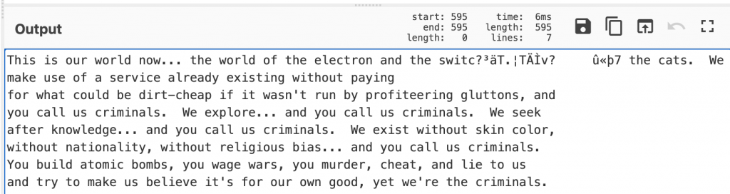
To illustrate this, we can encrypt a longer block of text (here on CyberChef).
Let’s change “baud” to “cats”. We need to locate the correct place in the ciphertext. AES (the encryption algorithm we are using) works in 16 byte blocks. The word “baud” is 85 characters in, so in the 6th block. We therefore want to modify the 5th block of ciphertext.
The exclusive OR is a bit more complex than last time – we now need to exclusive OR the ciphertext, the original text, and the desired text (here on CyberChef). But change those 4 bytes, and we change the word “baud” to “cats”.
The only issue is, as expected, the previous block has been entirely corrupted. Whilst in this case, it’s made part of the message nonsensical, it frequently has no impact when carrying out attacks.
But there are worse problems?
The above issue allows an attacker to modify the plaintext without detection. This would be an issue in certain situations, such as lock/unlock messages to a door.
But not authenticating your encryption can lead to worse issues. A type of attack called padding oracle attacks can let an attacker obtain the plaintext by sending a large number of specially crafted packets.
Block ciphers only operated on fixed blocks. If the data is shorter than a block, it must be padded. There are a number of ways of doing this, such as appending the number of padding bytes (e.g. 0x02 0x02 or 0x05 0x05 0x05 0x05 0x05). The process of decryption may check this padding is correct or not, and respond differently in each case.
An attacker can exploit these differential responses to leak the plaintext. This can break the confidentiality of messages.
What’s the solution to this?
Encryption should always be authenticated. There are two common solutions to this:
Add a Message Authentication Code (MAC). This is a keyed cryptographic checksum that provides authenticity and integrity.
Use an authenticated mode of operation such as GCM.
Even with this advice, there are many pitfalls. Applying the authentication and encryption in the wrong order can lead to weaknesses; this is so common that it has been deemed the Cryptographic Doom Principle.
Generally, developers shouldn’t be working with cryptography at this level unless they are suitably skilled. That’s easy to say, harder to put into action. There is a big movement to make use of secure-by-default cryptographic libraries and APIs that provide developers with useful functions without giving them so much rope they can hang themselves.
There are scant few reasons for not authenticating encryption.