I find reverse engineering is about building up a broad picture instead of working in-depth on any one aspect of the system. Dip into one bit, check what you are seeing is reliable and makes sense, dip into another area to get more detail, repeat.
We’ve done this with the logic trace – seen the long string sent, looked at the EEPROM access, checked what this in the .prm file, and seen that it is the ICCID. Now I would like to look at the firmware on the device.
CSL Dualcom have v353 hex file available for download on their site. The board I am looking at uses v202. That’s a big difference.
I can see a few paths here:
- Get a v202 (or anything nearer to v202 than v353) hex file downloaded. A quick Google doesn’t help here.
- Upgrade the board I have to v353. This would require the EEPROM to be updated, possibly other changes. I don’t want to break this board.
- Recover the v202 firmware from the board I have. There is a programming header – it could be possible to get the code off. But it may not be possible.
- Live with the difference and hope that there is enough consistency between the two to be helpful.
I’m going to run with 4. It’s the lowest effort, and I think it will work. The EEPROM structure between some of the different board seems identical – this is backed up by there only being a single Windows programming tool for the board, regardless of firmware version. In my experience, smaller embedded system firmware is quite consistent as new functionality is added, even if the toolchain changes (this really doesn’t hold true when you move up to anything bigger running Linux).
What can we do with the firmware? Well, we need to disassemble it. What does that actually mean? It means changing the raw machine code back into human-readable assembly language i.e. F7 becomes CLRW BC (clear register BC). This probably doesn’t meet everyone’s idea of human readable, but it is a lot better than machine code.
Some microcontrollers (like the ATmega series) have easy to understand and even read machine code. 90% of instructions are a fixed length (16bits). The number of instructions are limited and there are only limited addressing modes. With some practice you can make sense of machine code in text editor.
The 78K0R is not like this.

All of the enclosed red cells are MOV instructions. That’s a lot of them. There are 4 of these maps, with a total of 1024 cells. ~950 of them are populated.
There are several addressing modes and the instruction length varies from 8bits to 32bits. This makes the machine code incredibly hard to read.
We need an automated disassembler. Google isn’t much help here – these microcontrollers aren’t as popular as x86, ARM, AVR, or PIC .
There are two toolchains widely available for these processors. Renesas Cubesuite and IAR Embedded Workbench. There is a chance that one of these has either a disassembler or a simulator that allows a hex file to be loaded.
After a lot of messing around, it appears that Renesas Cubesuite can load the hex, disassemble it, and also simulate it.
1. Download Renesas Cubesuite and install it (Windows only)
2. Start Cubesuite.

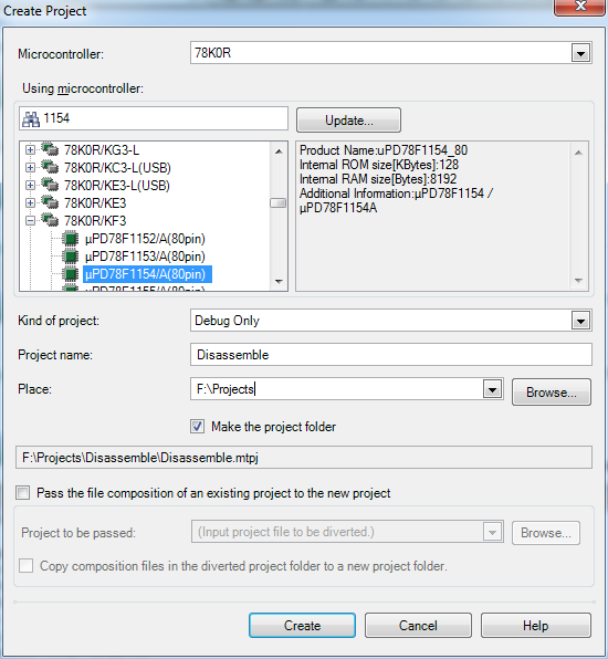
3. Go to Project -> Create new project.
4. Change the microcontroller to the “uPD78F1154_80” (the 80 pin variant)
6. Once the project has been created, in the “Project Tree” on the right hand side, right click on “Download files” and click “Add”
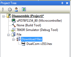
7. Find your hex or bin file and load it (hex is preferable as it seems the disassembler takes into account the missing address space).
8. Go to Debug -> Build and Download
9. The simulator starts up and you can see the disassembled code.
0e7e3        bd22        MOVW            0FFE22H,AX
0e7e5        17          MOVW            AX,HL
0e7e6        70          MOV             X,A
0e7e7        80          INC             X
0e7e8        61f8        SKNZ
0e7ea        5500        MOV             D,#0H
0e7ec        3149        SHL             A,4H
0e7ee        73          MOV             B,A
0e7ef        fa22        MOVW            HL,0FFE22H
0e7f1        8b          MOV             A,[HL]
0e7f2        fa22        MOVW            HL,0FFE22H
0e7f4        a7          INCW            HL
0e7f5        37          XCHW            AX,HL
0e7f6        bd22        MOVW            0FFE22H,AX
0e7f8        17          MOVW            AX,HL
0e7f9        70          MOV             X,A
0e7fa        80          INC             X
0e7fb        dd07        BZ              $0E804H
0e7fd        618d        XCH             A,D
Great – now we can get to work trying to see what the processor is doing.
The next post will likely be buzzing the board out to find out which I/O is connected to what so we can make some sense of the code.